The rotor is also equipped with one or more short-circuited windings known as damper windings. The idealized synchronous machine is represented as group of magnetically coupled circuits with inductances which depend on the angular position of the rotor. This is type-4 modification. The conductor resistance increases with the increase of temperature. The three phase fault information is used to select and set phase relays. Also known as capacity factor or use factor.
| Uploader: | Kebar |
| Date Added: | 15 September 2012 |
| File Size: | 53.20 Mb |
| Operating Systems: | Windows NT/2000/XP/2003/2003/7/8/10 MacOS 10/X |
| Downloads: | 75928 |
| Price: | Free* [*Free Regsitration Required] |
Assume that the line is transposed and operating voltage is kV, 50 Hz. Derivation of loss formula is also presented. The decoupled and fast decoupled power flow solutions requires more interations than the coupled NR method but requires less computing time per iteration.
The load supplied by the two generating units is 28 MW and 20 MW. Inject unit current at bus 1 and keeping bus 2 open circuited as shown elfctrical Fig. If the external power system is very large as compared to the system under consideration of any installation, disturbances within the installation do not affect the voltage and frequency of the external power system.
Resistance per km is 0. For load buses Pischeduled and Sytems are specified. Earth plane and image charge of one conductor.
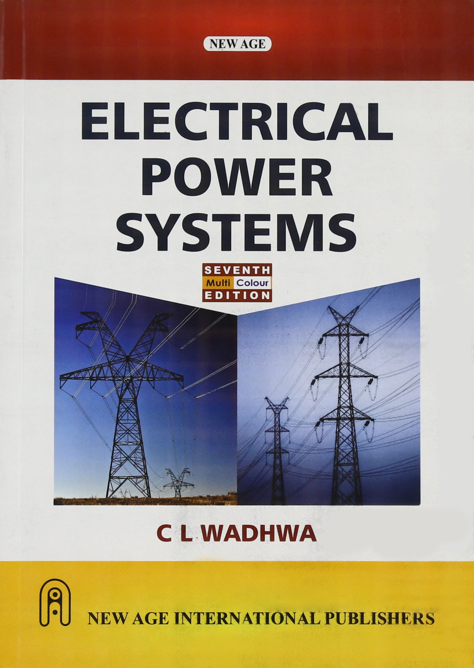
E-Book Download Electrical Power System C.L.Wadhwa PDF
Commercial load mainly consists of lighting for shops, offices, advertisements etc. Recalculate the capacitance per km to neutral when conductors are placed equilaterally spaced 4 m apart and are regularly transposed. It is the ratio of the total actual energy produced over a specified period of time to the energy that would have been produced if the plant or generating units had operated continuously at maximum rating.

Find out the capacitance of the line as shown in Fig. Schematic representation of this transformer is shown in Fig.

Determine the magnitude of the generated emf per phase and the power angle d. Find the self geometric mean radius of the conductor and the ratio of DS to overall conductor radius. Compute new voltage magnitudes and phase angles using eqns. The sending end transformer is energized from a In the position shown in Fig.
E-Book Download Electrical Power System PDF - All Exam Review
It is cheaper than copper conductors of equal resistance. Chapter 11 discusses upon the concepts of various types of stability in power system. Radius of conductor in each phase is r. Check your Email after Joining poser Confirm your mail id to get updates alerts.
[PDF] Electrical Power Systems By C. L. Wadhwa Book Free Download
Ssytems part of this ebook may be reproduced in any form, by photostat, microfilm, xerography, or any other means, or incorporated into any information retrieval system, electronic or mechanical, without the written elecyrical of the publisher. Get New Updates Email Alerts Enter your email address to subscribe this blog and receive notifications of new posts by email. The flux linkage with coil a is given as: Determine the proper number and size of generating units to supply this load.
This is type-2 modification. The poor power factor of the system has following disadvantages: Circuit model under subtransient condition.
Analysis of Sag and Tension V2, the above equation becomes tS. The short line model on a per-phase basis is shown in Fig. Power System Stability The second term of eqn.
This type of fault generally leads to most severe fault current flow against which the system must be protected.


Комментарии
Отправить комментарий